
|
Virtual Peripherals |
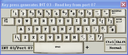
| Keyboard Port 07 INT 03 |
 |
| How to Use |
| This is one of the more complex devices. To make the keyboard visible,
use OUT 07. Every time a key is pressed, a hardware interrupt,
INT 03 is generated. By default, the CPU will ignore this
interrupt. To process the interrupt, at the start of the program, use the
STI command to set the interrupt flag (I) in the CPU status
register (SR). Place an interrupt vector at RAM address 03.
This should point to your interrupt handler code. The interrupt handler
should use IN 07 to read the key press into the AL
register. Once STI has set the (I) flag in the status register (SR), interrupts from the hardware timer will also be generated. These must be processed too. The hardware timer generates INT 02. To process this interrupt, place an interrupt vector at RAM location 02. This should point to the timer interrupt handler code. The timer code can be as simple as IRET. This will cause an interrupt return without doing any other processing. jmp start db 10 ; Hardware Timer Interrupt Vector db 20 ; Keyboard Interrupt Vector ; ===== Hardware Timer ======= org 10 nop ; Do something useful here nop nop nop nop iret ; ============================ ; ===== Keyboard Handler ===== org 20 CLI ; Prevent re-entrant use push al pushf in 07 nop ; Process the key press here nop nop nop nop popf pop al STI iret ; ============================ ; ===== Idle Loop ============ start: STI ; Set (I) flag out 07 ; Make keyboard visible idle: nop ; Do something useful here nop nop nop nop jmp idle ; ============================ end ; ============================ |
| Visual Display Unit Memory Mapped |
How to Use |
 |
The Visual Display Unit (VDU) is memory mapped. This means that RAM locations correspond to positions on the screen. RAM location C0 maps to the top left corner of the VDU. The screen has 16 columns and four rows mapped to RAM locations C0 to FF. When you write ASCII codes to these RAM locations, the corresponting text characters appear and the VDU is made visible. This device, when combined with a keyboard, is sometimes called a dumb terminal. It has no graphics capabilities. Here is a code snippet to write text to the screen. ; ===== Memory Mapped VDU ===================================================== MOV AL,41 ; ASCII code of 'A' MOV [C0],AL ; RAM location mapped to the top left corner of the VDU MOV AL,42 ; ASCII code of 'B' MOV [C1],AL ; RAM location mapped to the VDU MOV AL,43 ; ASCII code of 'C' MOV [C2],AL ; RAM location mapped to the VDU END ; ============================================================================= |
| Traffic Lights Port 01 |
How to Use |
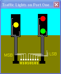 |
The traffic lights are connected to Port 01. If a byte of data is sent to this port, wherever there is a one, the corresponding traffic light comes on. In the image on the left, the binary data is 01010101. If you look closely you can see that the lights that are on, correspond to the ones in the data byte. 01010101 is 55 hexadecimal. Hex' numbers are explained here. Here is a code snippet to control the lights. ; =========================================================================== ; ===== 99Tlight.asm ======================================================== ; ===== Traffic Lighte on Port 01 =========================================== Start: MOV AL,55 ; 01010101 OUT 01 ; Send the data in AL to Port 01 (the traffic lights) MOV AL,AA ; 10101010 OUT 01 ; Send the data in AL to Port 01 (the traffic lights) JMP Start END ; =========================================================================== |
| Seven Segment Displays Port 02 |
How to Use |
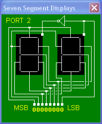 |
The seven segments displays are connected to Port 02. If a byte of data is sent to this port, wherever there is a one, the corresponding segment comes on. The rightmost bit controls which of the two groups of segments is active. This is a simple example of mulitplexing. If the least significant bit (LSB) is zero, the left segments will be active. If the least significant bit (LSB) is one, the right segments will be active. Here is a code snippet. ; ====================================================== ; ===== 99sevseg.asm =================================== ; ===== Seven Segment Displays Port 02 ================= Start: MOV AL,FA ; 1111 1010 OUT 02 ; Send the data in AL to Port 02 MOV AL,0 ; 0000 0000 OUT 02 ; Send the data in AL to Port 02 MOV AL,FB ; 1111 1011 OUT 02 ; Send the data in AL to Port 02 MOV AL,1 ; 0000 0001 OUT 02 ; Send the data in AL to Port 02 JMP Start END ; ====================================================== |
| Heater and Thermostat Port 03 |
How to Use |
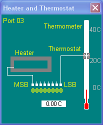 |
The heater and thermostat system is connected to Port 03. Send 00 to port 3 to turn the heater off. Send 80 to port 03 to turn the heater on. Input from port 03 to test the thermostat state. The code snippet below is an incomplete solution to control the heater to keep the temperature steady at about 21 C. You can click the thermometer to set the temperature. This can save time when you are testing the system. ; ===== Heater and Thermostst on Port 03 ========================== ; ===== 99Heater.asm ============================================== ; ===== Heater and Thermostst on Port 03 ========================== MOV AL,0 ; Code to turn the heater off OUT 03 ; Send code to the heater IN 03 ; Input from Port 03 AND AL,1 ; Mask off left seven bits JZ Cold ; If the result is zero, turn the heater on HALT ; Quit Cold: MOV AL,80 ; Code to turn the heater on OUT 03 ; Send code to the heater END ; ================================================================= |
| Snake and Maze Port 04 |
How to Use |
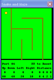 |
The left four bits control the direction of the snake.
The right four bits control the distance moved. For example, 4F means Down 15. 4 means down. F means 15. This program is rather wasteful of RAM. If you want to traverse the entire maze and go back to the strart, you will run out of RAM. A good learning task is to use a data table. This reduces the size of the program greatly. Also, it is good style to separate code and data. Here is a code sample - not using a data table. ; ================================================================ ; ===== 99snake.asm ============================================== ; ===== Snake and Maze =========================================== Start: MOV AL,FF ; Special code to reset the snake. OUT 04 ; Send AL to port 04 to control the snake. MOV AL,4F ; 4 means DOWN. F means 15. OUT 04 ; Send 4F to the snake OUT 04 ; Send 4F to the snake OUT 04 ; Send 4F to the snake OUT 04 ; Send 4F to the snake JMP Start END ; ================================================================ |
| Stepper Motor Port 05 |
How to Use |
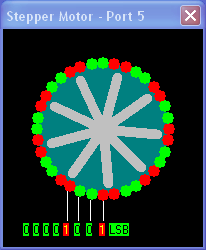 |
Here is a stepper motor. Normal motors run continuously and it is hard to control their movement. Stepper motors step through a precise angle when electromagnets are energised. Stepper motors are used for precise positional control in printers, plotters, robotic devices, disk drives and for any application where precise positional accuracy is required. The motor is controlled by energising the four magnets in turn. It is possible to make the motor move in half steps by energising single and pairs of magnets. If the magnets are energised in the wrong sequence, the motor complains by a bleep from the computer speaker. Here is a code snippet to control the motor. Note that it would be better coding style to use a data table. ; ================================ ; ===== 99Step.asm =============== ; ===== Stepper Motor ============ mov al,1 out 05 mov al,2 out 05 mov al,4 out 05 mov al,8 out 05 mov al,9 out 05 mov al,1 out 05 mov al,3 out 05 mov al,2 out 05 mov al,6 out 05 mov al,4 out 05 mov al,c out 05 mov al,8 out 05 mov al,9 out 05 mov al,1 out 05 end ; ================================ |
| Lift/Elevator Port 06 |
How to Use |
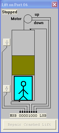 |
Input Signals Bits 8 and 7 are unused. Bit 6 is wired to the top call button. Bit 5 is wired to the bottom call button. If these buttons are clicked with the mouse, the corresponding bits come on. Bit 4 senses the lift and goes high when the lift cage reaches the bottom of the shaft. Bit 3 senses the lift and goes high when the lift cage reaches the top of the shaft. Outputs Bit 2 turns on the lift motor and the cage goes down. Bit 1 turns on the lift motor and the cage goes up.
Ways To Destroy the Lift
|
| Hardware Timer INT 02 |
How to Use |
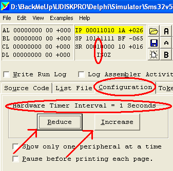 |
The hardware timer generates INT 02 at regular time
intervals. The time interval can be changed using the Configuration tab
as shown in the image. The CPU will ignore INT 02 unless
the (I) flag in the status register (SR) is set. Use STI
to set the (I) flag. Use CLI to clear the (I) flag. The code sample below processes INT 02 but does nothing useful. If the CPU clock is too slow, a new INT 02 can occur before the previous one has been handled. This is not necessarily a problem as long as the CPU eventually catches up. To allow this to work, it is essential that the interrupt handler saves and restores any registers it uses. Use PUSH and PUSF to save registers. Use POPF and POP to restore registers. Remember to pop items in the reverse order that they were pushed. Code like this is "re-entrant". If the CPU is too slow and does not catch up, the stack will gradually grow and eat up all the available RAM. Eventually the stack will overwrite the program causing a crash. It is a useful learning exercise to slow the CPU clock and watch this happen. jmp start db 10 ; Hardware Timer Interrupt Vector ; ===== Hardware Timer ======= org 10 nop ; Do something useful here nop nop nop nop iret ; ============================ ; ===== Idle Loop ============ start: STI ; Set (I) flag idle: nop ; Do something useful here nop nop nop nop jmp idle ; ============================ end ; ============================ |
| Numeric Keypad Port 08 INT 04 |
How to Use |
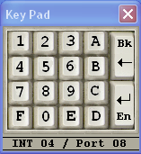 |
This is one of the more complex devices. To make the numeric keypad visible,
use OUT 08. Every time a key is pressed, a hardware interrupt,
INT 04 is generated. By default, the CPU will ignore this
interrupt. To process the interrupt, at the start of the program, use the
STI command to set the interrupt flag (I) in the CPU status
register (SR). Place an interrupt vector at RAM address 04.
This should point to your interrupt handler code. The interrupt handler
should use IN 08 to read the key press into the AL
register. Once STI has set the (I) flag in the status register (SR), interrupts from the hardware timer will also be generated. These must be processed too. The hardware timer generates INT 02. To process this interrupt, place an interrupt vector at RAM location 02. This should point to the timer interrupt handler code. The timer code can be as simple as IRET. This will cause an interrupt return without doing any other processing. jmp start db 10 ; Hardware Timer Interrupt Vector db 00 ; Keyboard Interrupt Vector (unused) db 20 ; Numeric Keypad Interrupt Vector ; ===== Hardware Timer ======= org 10 nop ; Do something useful here nop nop nop nop iret ; ============================ ; ===== Keyboard Handler ===== org 20 CLI ; Prevent re-entrant use push al pushf in 08 nop ; Process the key press here nop nop nop nop popf pop al STI iret ; ============================ ; ===== Idle Loop ============ start: STI ; Set (I) flag out 08 ; Make keypad visible idle: nop ; Do something useful here nop nop nop nop jmp idle ; ============================ end ; ============================ |
© C Neil Bauers 2003