
|
System Architecture |
The simulator is programmable in that you can run many different programs. In real life, the RAM would be replaced by read only memory (ROM) and the system would only ever run one program hard wired into the ROM. There are hundreds of examples of systems like this controlling traffic lights, CD players, simple games consoles, many children's games, TV remote controls, microwave oven timers, clock radios, car engine management systems, central heating controllers, environmental control systems and the list goes on.
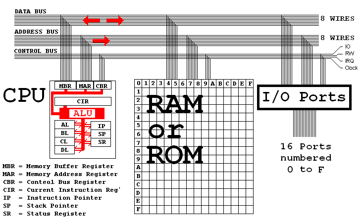
The central processing unit is the "brain" of the computer. All calculations, decisions and data moves are made here. The CPU has storage locations called registers. It has an arithmetic and logic unit (ALU) where the processing is done. Data is taken from the registers, processed and results go back into the registers. Move (MOV) commands are used to transfer data between RAM locations and the registers. There are many instructions, each with a specific purpose. This collection is called the instruction set.
The CPU has four general-purpose registers called AL, BL, CL and DL. These are eight bits or one byte wide. Registers can hold unsigned numbers in the range 0 to +255 and signed numbers in the range –128 to +127. These are used as temporary storage locations. Registers are used in preference to RAM locations because it takes a relatively long time to transfer data between RAM and the CPU. Faster computers generally have more CPU registers or memory on the CPU chip.
The registers are named AL, BL, CL and DL because the 16-bit version of this CPU has more registers called AH, BH, CH and DH. The 'L' means Low and the 'H' means High. These are the low and high ends of the 16-bit register.
The special purpose registers in the CPU are called IP, SR and SP.
This register contains the address of the instruction being executed. When execution is complete, IP is increased to point to the next instruction. Jump instructions alter the value of IP so the program flow jumps to a new position. CALL and INT also change the value stored in IP. In the RAM displays, the instruction pointer is highlighted red with yellow text.
This register contains flags that report the CPU status.
The 'Z' zero flag is set to one if a calculation gave a zero result.
The 'S' sign flag is set to one if a calculation gave a negative result.
The 'O' overflow flag is set if a result was too big to fit in a register.
The 'I' interrupt is set if interrupts are enabled. See CLI and STI.
The stack is an area of memory organised using the LIFO last in first out rule. The stack pointer points to the next free stack location. The simulator stack starts at address BF just below the RAM used for the video display. The stack grows towards address zero. Data is pushed onto the stack to save it for later use. Data is popped off the stack when needed. The stack pointer SP keeps track of where to push or pop data items. In the RAM displays, the stack pointer is highlighted blue with yellow text.
The simulator has 256 bytes of ram. The addresses are from 0 to 255 in decimal numbers or from [00] to [FF] in hexadecimal. RAM addresses are usually given in square brackets such as [7C] where 7C is a hexadecimal number. Read [7C] as "the data stored at location 7C".
Busses are collections of wires used to carry signals around the computer. They are commonly printed as parallel tracks on circuit boards. Slots are sockets that enable cards to be connected to the system bus. An 8-bit computer typically has registers 8 bits wide and 8 wires in a bus. A 16-bit computer has 16 bit registers and 16 address and data wires and so on. The original IBM PC had 8 data wires and 20 address wires enabling one megabyte of RAM to be accessed. 32 bit registers and busses are now usual (1997-2003).
Data Bus |
The Data Bus is used to carry data between the CPU, RAM and IO ports. The simulator has an 8-bit data bus. |
Address Bus |
The Address Bus is used to specify what RAM address or IO port should be used. The simulator has an 8-bit address bus. |
Control Bus |
The Control Bus This has a wire to determine whether to access RAM or IO ports. It also has a wire to determine whether data is being read or written. The CPU reads data when it flows into the CPU. It writes data when it flows out of the CPU to RAM or the IO ports. The System Clock wire carries regular pulses so that all the electronic components can function at the correct times. Clock speeds between 100 and 200 million cycles per second are typical (1997). This is referred to as the clock speed in MHz or megahertz. The simulator runs in slow motion at about one instruction per second. This is adjustable over a small range. |
Hardware Interrupts |
Hardware Interrupts require at least one wire. These enable the CPU to respond to events triggered by hardware such as printers running out of paper. The CPU processes some machine code in response to the interrupt. When finished, it continues with its original task. The IBM PC has 16 interrupts controlled by 4 wires. |
© C Neil Bauers 2003